Above is my talk about this project, as given at the Graphics Programming Virtual Meetup. If you read the writeup on the implementation of the 2d softbodies, you will have seen that it really served as a prototype for the ideas used in this project. I have not implemented as many different models, just the vehicle chassis, but the framework is in place to do 3d analogs of what I was doing in 2d (bridge truss, cloth). I won’t get as much into the theory, since it is almost entirely the same as the previous project, but now with OpenGL hardware accelerated 3D output.
GENERATING THE MODEL
In the previous project, I generated the models by drawing them out on paper or on a whiteboard, or opened them in GIMP and picked pixel offsets as the X and Y positions of some selected points on the model. I then added the edges between the relevant nodes and that was the model. I could set the spring constants and damping rates, but it was on a per-edge basis so the ability to orchestrate it at a higher level was difficult. It was not at all an efficient process and required a fair amount of time to go from working on paper to having a reasonable model in the program. This does not scale well - designing 3d models this way quickly becomes impractical.
As a result, I had to figure out different tools. I generated the model of the vehicle chassis in Blender – using the mirror modifier and modleing with individual verticies and manually creating edges between them, I was able to get what I think is a reasonable 3d analog to the 2d chassis I had laid out. The OBJ export feature of Blender is a big deal, in this context – it turns out, the way they represent points and edges in the Wavefront OBJ format is almost identical to the approach that I was using – very little conversion was required.
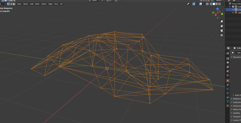
The format has some header information, followed by a list of points – there are a lot more pieces of information that can be included on a per-vertex basis but for my purposes I only needed vertex positions. After the vertex info, there’s a listing of the edges – each edge is specified by two numbers, which are 1-indexed into the list of verticies. Subtracting 1 was the only conversion necessary to get 0-indexed values like I was using.
I used this method to generate the points on the chassis – the suspension links were generated separately. I set up a quick tool to let me iterate through the individual verticies, highlighting them and report the index of the highlighted vertex to the command line – I used this to figure out which of the chassis points should be connected to the wheel anchors by the suspension edges. By enabling GL_PROGRAM_POINT_SIZE, you can set gl_PointSize in your vertex shader to further emphasize the selected vertex.
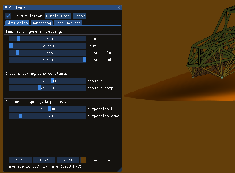
By treating these as two sets of edges, the chassis links and the suspension links separately, I was able to set up sliders to set the two sets of spring rates and damping constants.
C++ IMPLEMENTATION
Similar to Voraldo 1.0, I used Dear Imgui to do the graphical user interface. As a very flexible drop-in utility, I’ve had a lot of success using it to allow runtime interaction with my OpenGL applications at a higher level than just using SDL’s event system to handle input. One important way this manifests is inputting numbers, strings and other values, because keeping them otherwise would have to be handled on a per-event basis and that becomes very labor intesive - much easier to get this functionality from something at a higher level like dear imgui handles it.
My softbody update is very similar to the 2d version - I decided to make a change to double precision vectors in an effort to make a more stable system (I haven't seen much difference in this particular case). The primary differences are in the rendering method - for details on the simulation, see the other writeup. Each frame, after the update is computed, the current vertex positions are cast as floats and sent in a batch to the GPU to be used as position vertex attributes. I am rendering these lines twice, with different line widths, in order to achieve the thin black outline around all the segments. I find this helps delineate between lines that would otherwise be over top of lines exactly the same color (vs having no distinction between those neighboring fragments).
The wheel's positions, again, are displaced by perlin noise. By doing this, I can have smooth movement, and using the sliders in the interface I can scale the amplitude and change the frequency of how this noise function is evaluated. The offsets are only applied perpendicular to the XZ plane - I added some points rendered in a grid, using this same offset, to help visualize where this perlin noise 'ground' would be.
Since this was written, I have figured out OpenGL SSBOs for my physarum sim project, and given the parallelizability of this approach I want to return to this to do the computation directly on the GPU once I have some more experience with these and can get my mind around handling the data this way.
UPDATE (6/29/2020): I went through and figured out how to multithread the update function. However, I actually saw a slowdown when running the threaded update versus the unthreaded update. My working theory is that with the limited number of points (about 10, which is very small, and really not that much work is done for each point) that are involved in each thread's update, the overhead of creating and joining threads is actually greater than the speedup that you would see. I could be mistaken, but this is what I think is happening.