GPU SDF Pathtracing: Refraction - WIP
This was my next step after getting pathtracing with basic materials done. Continuing on with an SDF based model for geometry, this part of the project introduces a separate distance estimator which represents the refractive materials, defined in the same space as the rest of the geometry. By having these as two separate entities, there are two distinct types of geometry intersections that can happen: normal and refractive (refractive has two types, but we will get there).
Vessica Picis
There's a classical shape from gothic architecture which is the intersection of two circles of the same radius. I'm not sure what spurred my initial interest, but this inspired the method by which I formed the lens shape. Extending the idea of the vessica picis two three dimensions, I used the intersection of two sphere SDFs. In my implementation, the two spheres can have different radii, and are separated by some lens thickness. Their centers are separated by radius1 + radius2 - thickness. As you can see, the use of two distinct radii creates different curvature on either side of the lens - this will create different refractive behavior for viewer positions on either side. For the purposes of this discussion, this is the refractive object that I will be dealing with.
Refraction
Refraction is a phenomena that occurs with light rays, by which the direction bends at interface changes. These interfaces exist between materials with different index of refraction (IOR) values. These types of materials are called 'dielectric'. IOR is a ratio of how quickly light can pass through this material, relative to the speed of light in a vacuum. By specifiying this quantity for the lens, and assuming a value of 1.0 for the surrounding 'air', we have now established a partitioning of the space. Independent of the rest of the scene geometry, there is 'inside the lens' and 'outside the lens'.
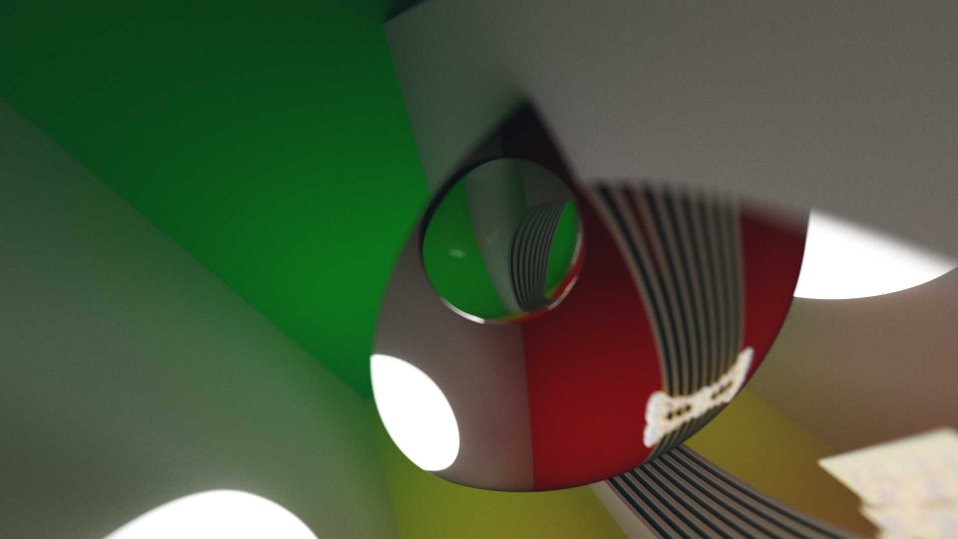
As light passes through these interfaces between dielectric materials, these bends will affect the direction of the ray as it continues farther into the scene. As you can see in the images above and below, this can create a magnification effect, as the rays have effectively diverged out from one another, spreading out and becoming less parallel. This plays interestingly with the DoF calculations, as well as creating some interesting visual distortion, as you can see here.
Stateful Implementation & Room for Improvement
As I previously alluded to, there are now a few different distinct signed distance functions. It simply involves taking the min() of a bunch of calculated distance estimates, keeping track of which one is 'closest'. This 'closest' surface will have some logic associated with it, distinct from other surfaces. I had already employed this method for the application of materials, to guide the rays in a sampled diffuse or specular reflection. Now the model has been extended to consider refractive objects, by keeping a global flag telling whether or not the ray is currently inside of a refractive object. The flag is set on a refractive hit, and unset on the next refractive hit, which is taken as hitting the back face, the other side of the inside of the object.
After some time away from implementing this project, I have some more insight into ways this refractive hit logic might be improved - for example, this front/back face distinction can be drawn by taking a sample of the normal, which comes from the gradient of the signed distance field, and the ray direction. Take the dot product of the two vectors - your result will tell you whether that result is acute or obtuse. If the angle is obtuse, the rays are traveling in different directions. That can be understood geometrical as a situation where this incident ray is coming in and hitting the front face. Correspondingly, you have the opposite logic for acute angles, where they are pointing the same direction. If the incident ray is going the same direction as the normal, it is coming from inside the object.
As I described, I currently use a global flag to maintain state. This may need to stay. The logic I use for the inside of refractive objects is very simple - it inverts the return value for the SDF with the state of this global flag. This allows for light to enter and interact with objects embedded in the refractive objects with the same surface behavior that they would have outside of the lens.
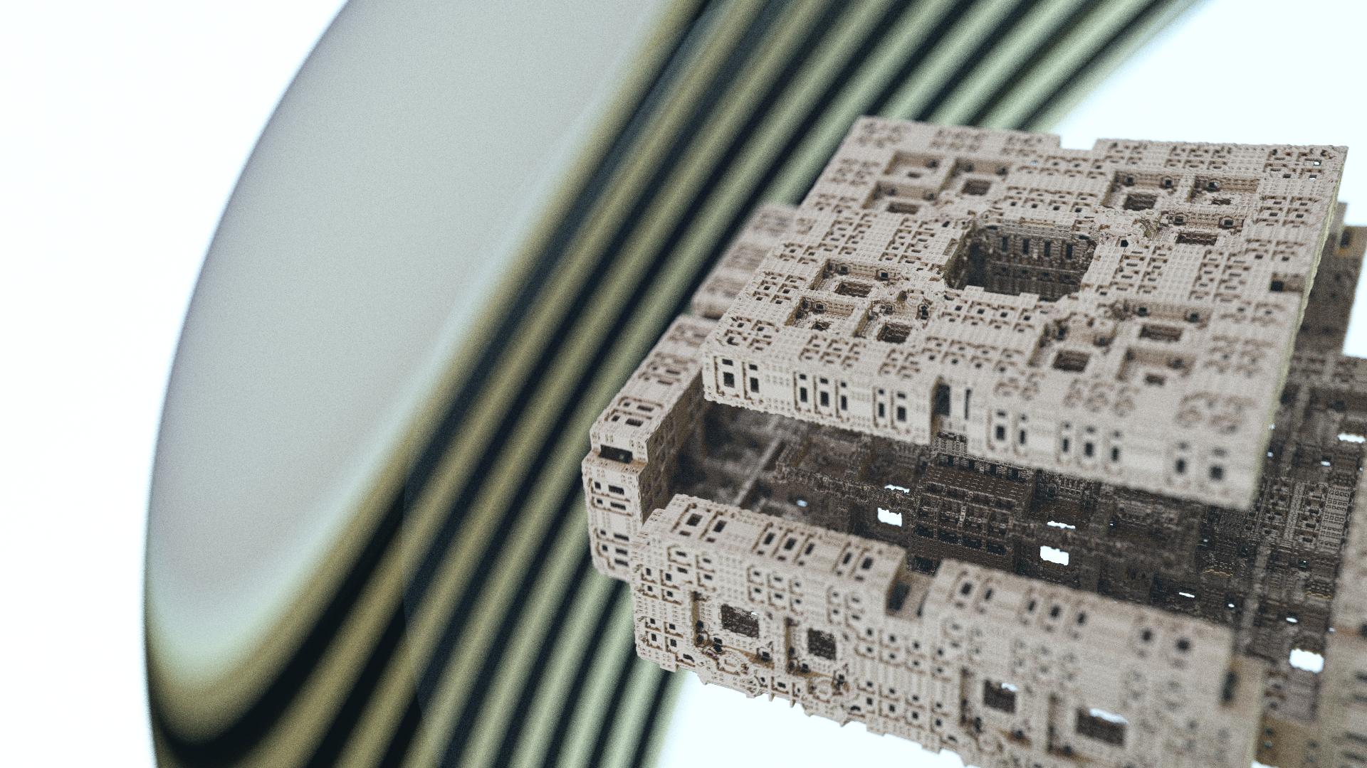
Fractal Limitations
Something I was interested to try, was using some fractal SDFs as refractive objects. Due to the way they fold the space, the distance bounds don't always hold correctly, or the SDF is all 0 inside - different failure modes, but it doesn't work by trivially applying the logic I described above. I have been talking with some people about a method which does the same thing, but inside of refractive objects, you take a constant size step until you either have a hit or leave the refractive object.
A Limited Model for Nested Dielectrics
Something that has come across my radar a few times over the past few years, is the concept of nested dielectrics. That is, dielectric materials of varying IOR, in the same scene, the ray refraction logic implemented by keeping some kind of model of the relative IOR at these interface changes.
I have achieved a few results which get close to this effect. I think that in the future, I will be able to improve on this. I have seen some methods which keep a stack as a model, and from what I understand, that has some merit. I do think it bears revisiting.
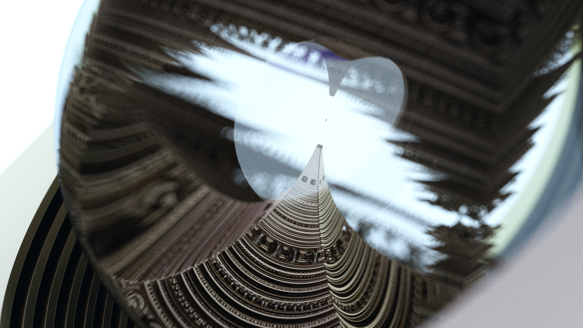
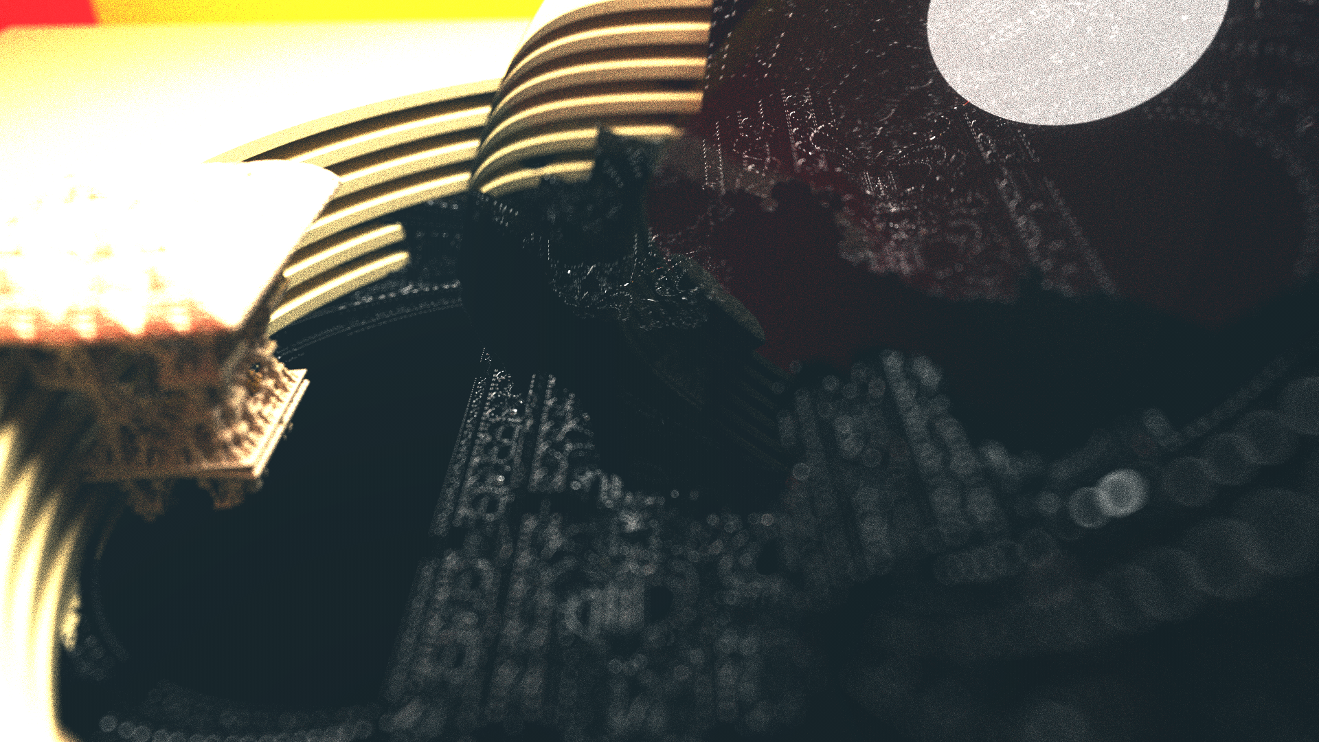
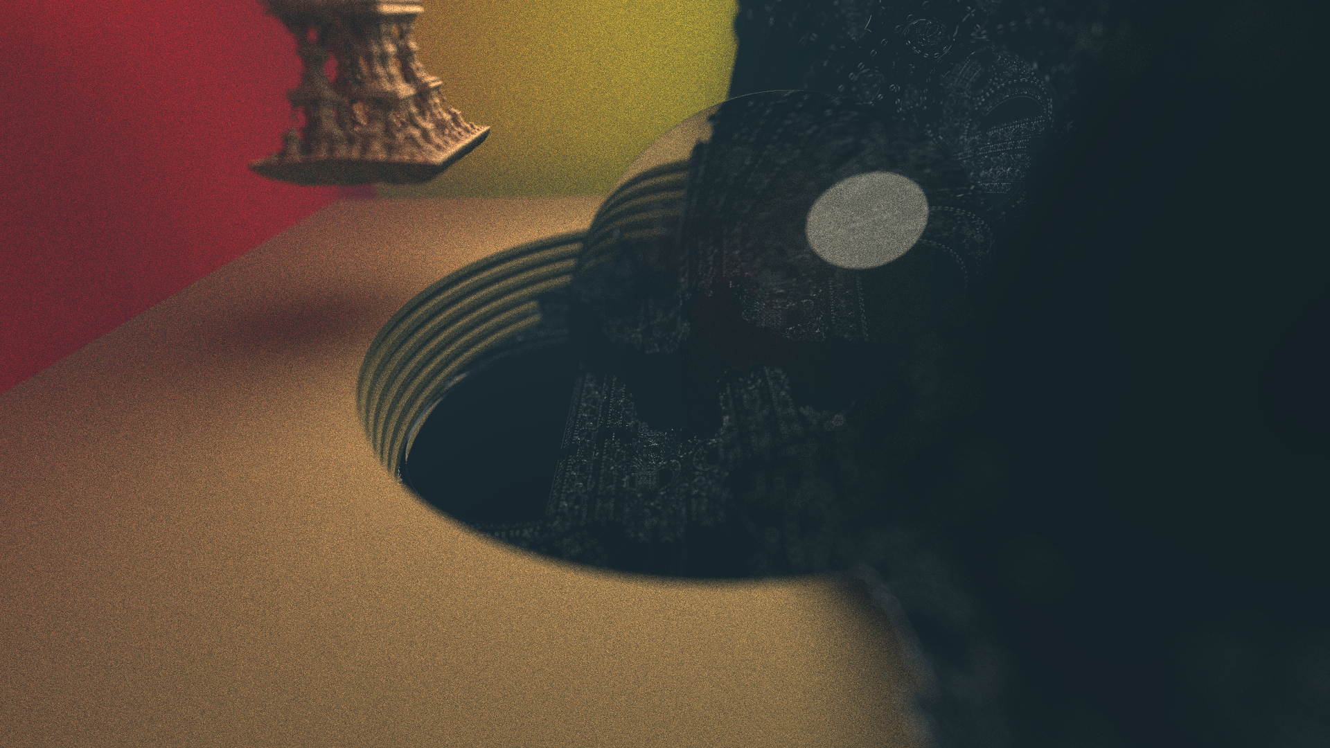
Viewer Inside the Lens
This is part of what creates the apparent nested dielectric effect. The appearance of the bubbles here is caused by an interface change where the ray is coming from a material with an IOR of less than 1.0, entering a material with a greater IOR. The same can be achieved by creating the same situation with the viewer outside the lens, with a lens IOR less than 1.0, as you can see in this first image here.
You start to see more surreal consequences from the total internal reflection (TIR), with the viewer inside the lens, though, and you will begin to see things that don't make much sense to your typical spatial understanding. It could be modelled by looking into air, from underwater.
When the ratios are adjusted beyond what makes sense for any kind of physical material, you can get some interesting warping that leads to these highly curved spaces. I think there's a lot of potential here for some very cool images.
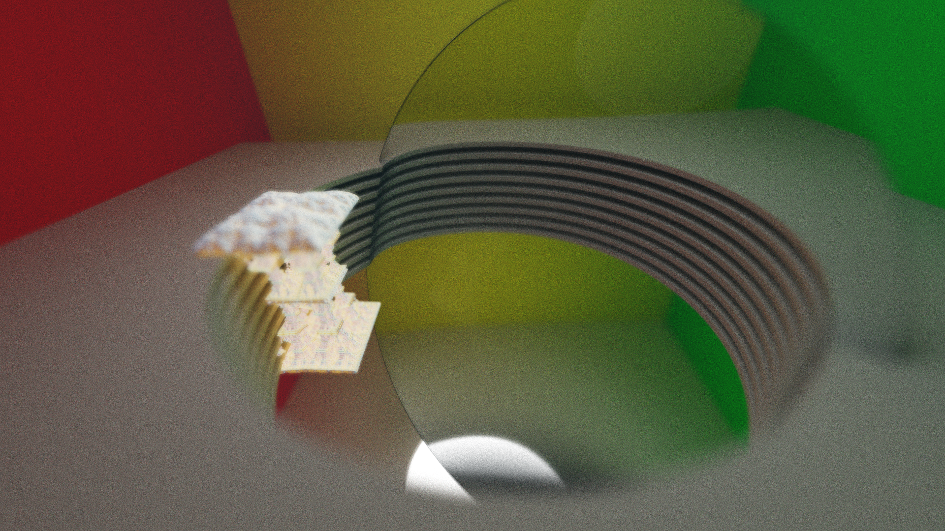
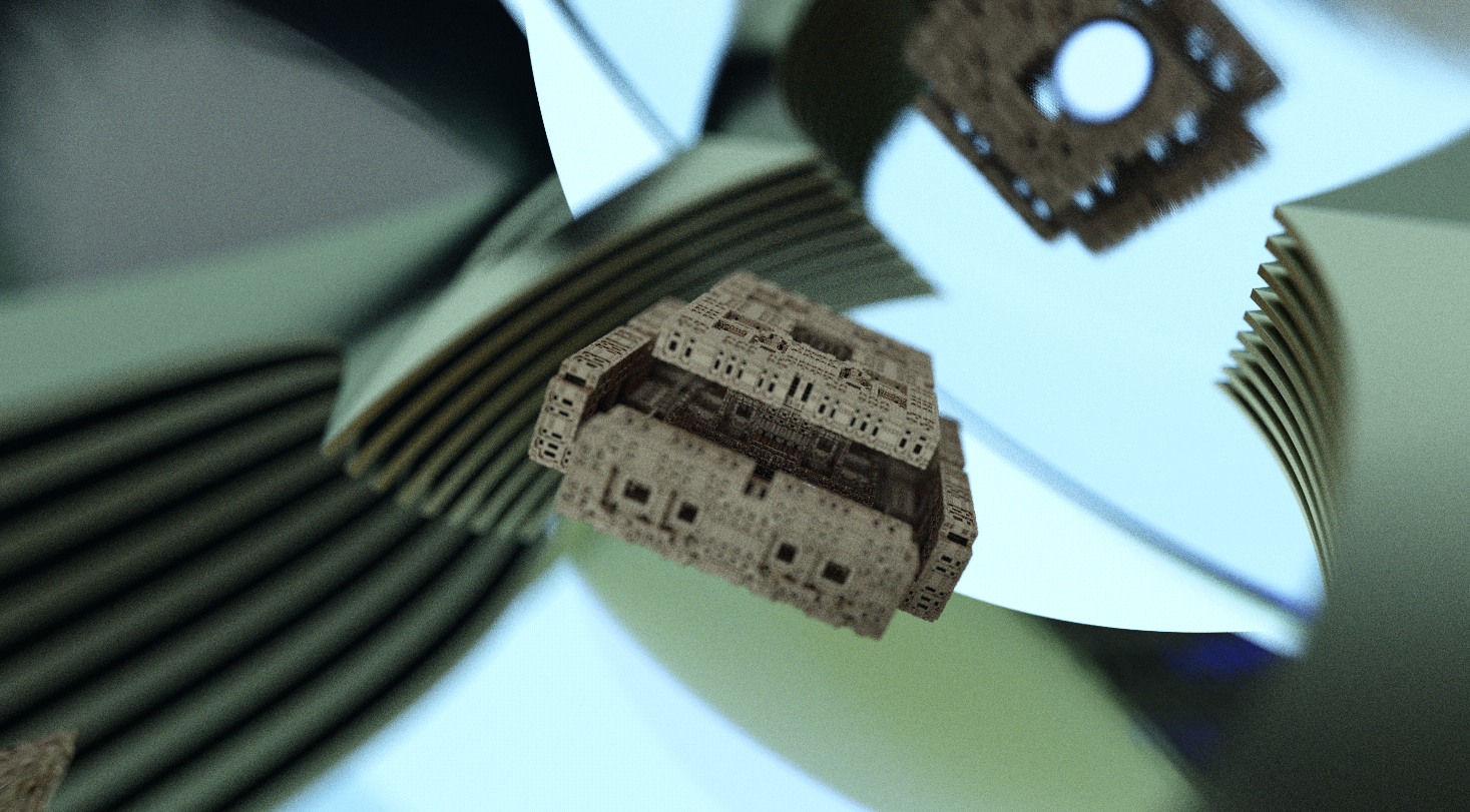
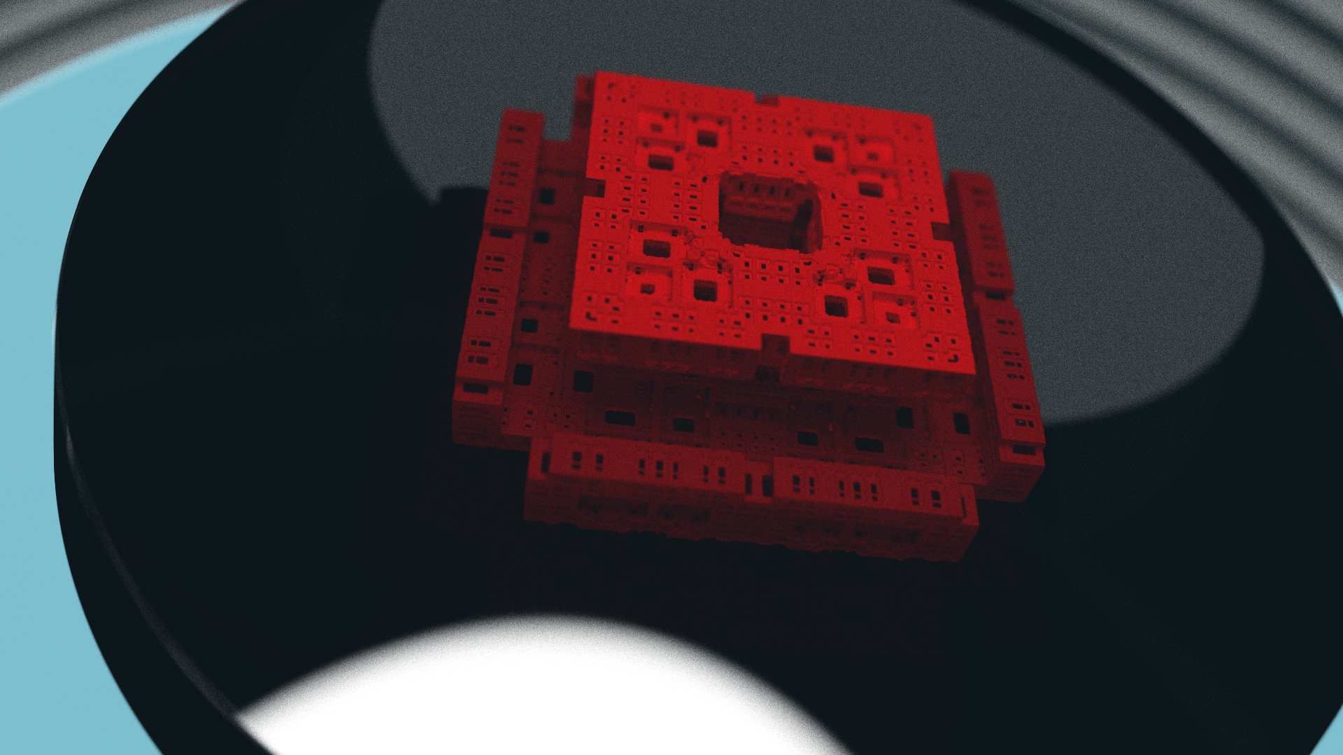
Objects Embedded in Lens
This is another method in which I played with the refractive obects. By intersection regular scene geometry with the lens DE, I was able to create some interesting effects. The refraction logic was robust to these changes, and didn't need any adaptation.
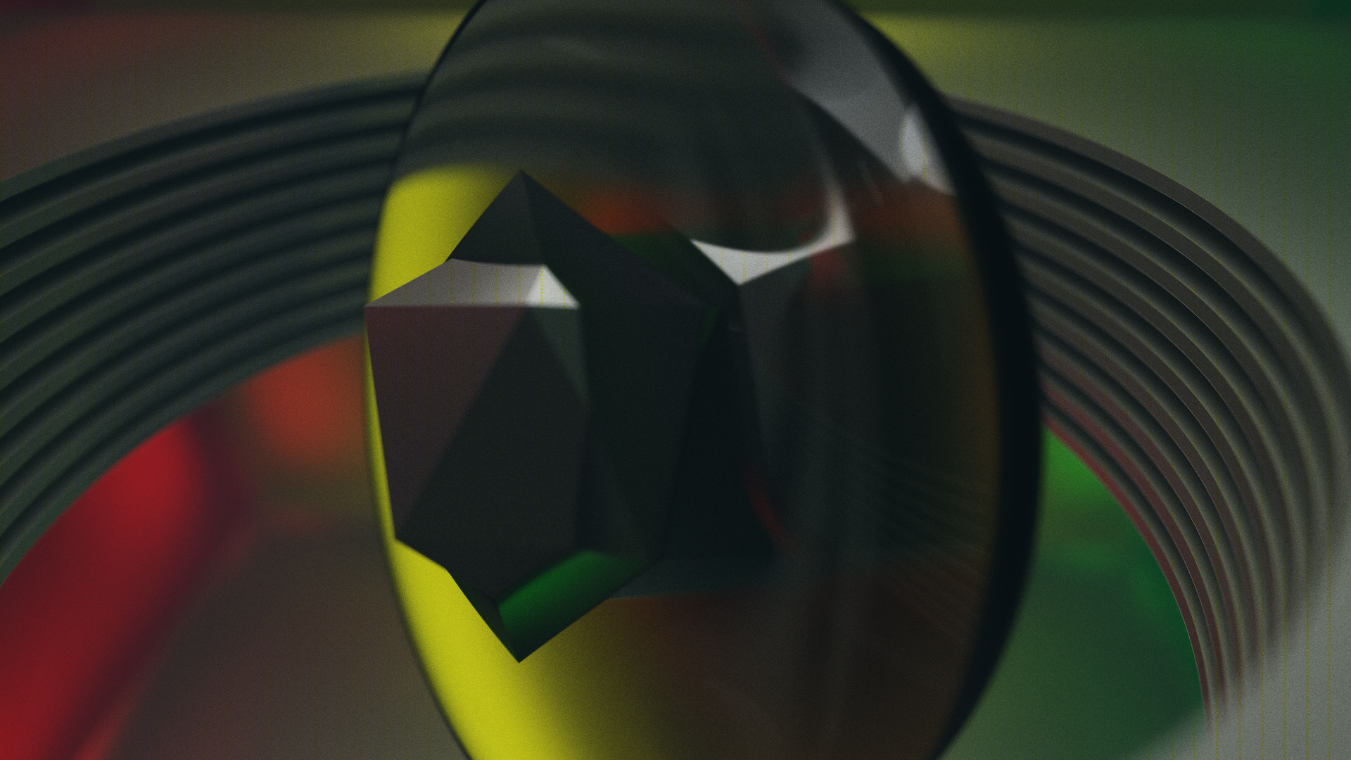
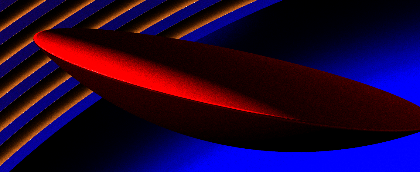
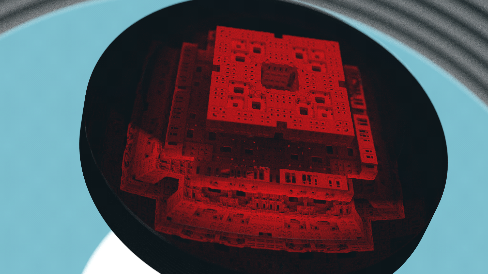
You can see some of the types of distortion that is applied - here, above, with the icosahedron, the lower face appears to take on a curve, like a knife bevel. In reality, this is a flat surface, and the curve is actually an artifact of the fact that the rays had to pass through a refractive surface of varying curvature to get to that face.
You can see the difference between the above and below images - the only difference is an adjustment of IOR. The very top of the object pokes through the surface of the lens, but you can see how the TIR creates a parabolic mirror type of effect on the back face. This particular type of zoom effect is kind of interesting and actually is very similar to some things I tried while implementing perspective projection in Voraldo, which modelled inverse aka byzantine perspective, where rays toe inwards instead of diverging with distance.
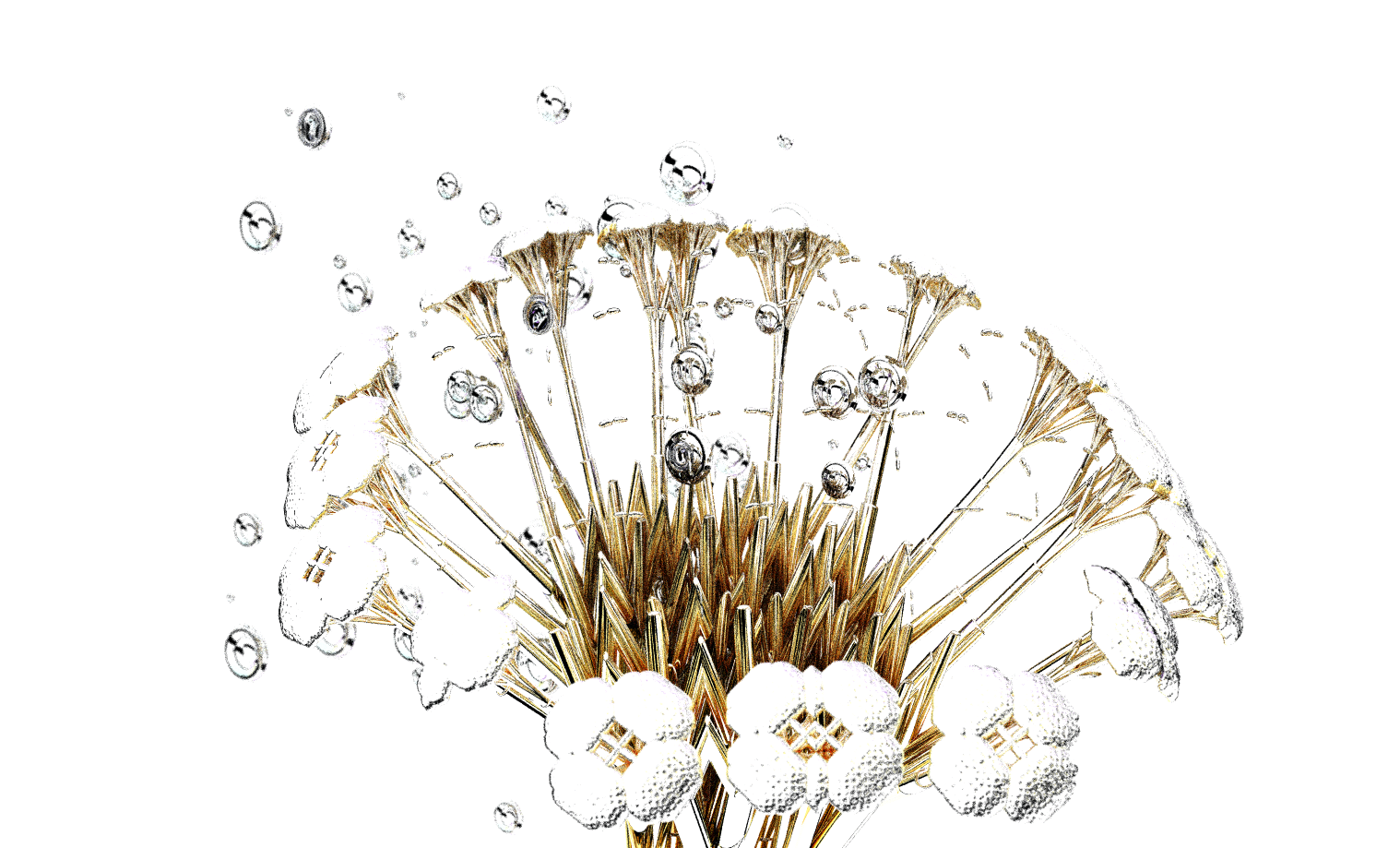
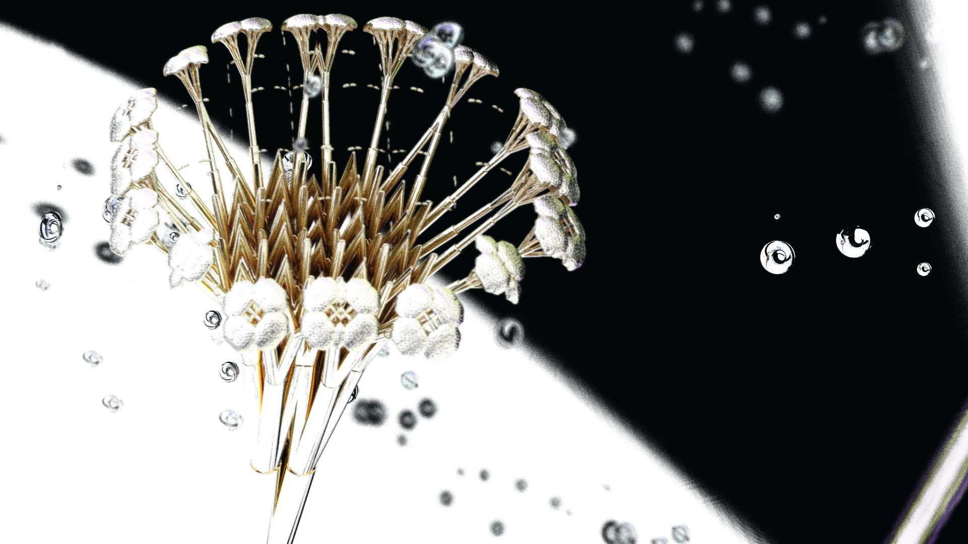
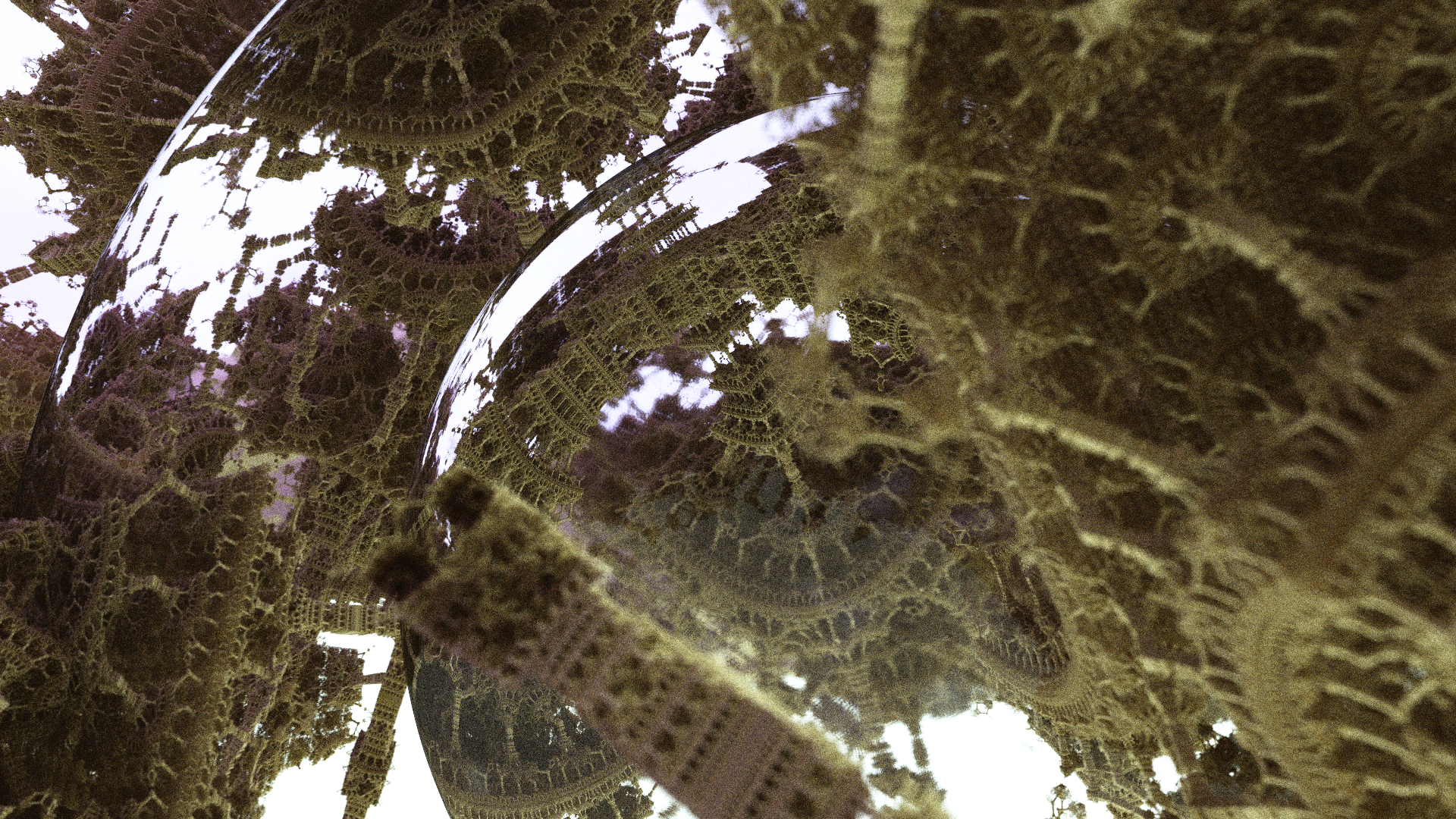
Weird Stuff
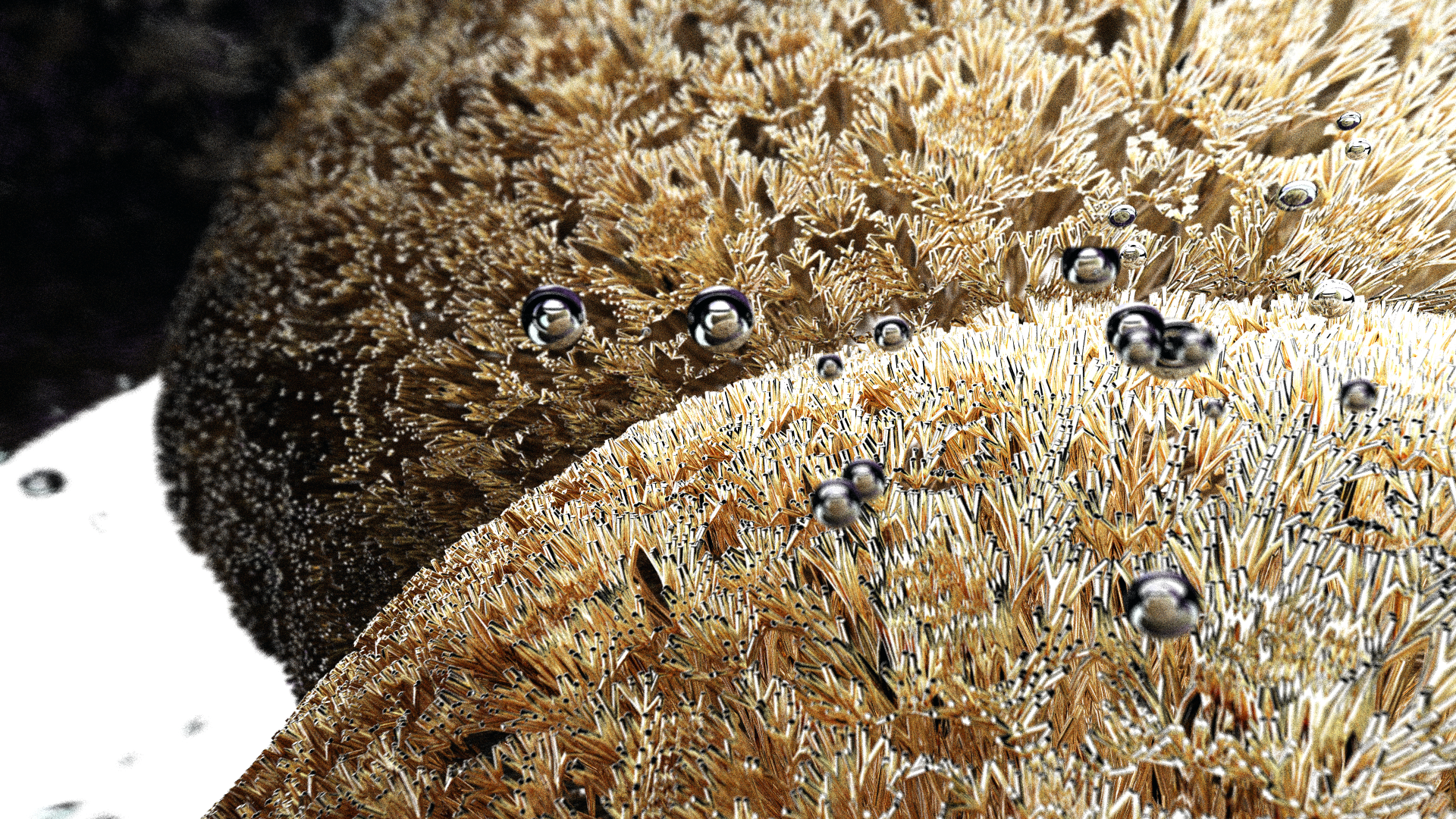
This came from playing with IOR values, again. The basic scene setup is an infinitely repeating fractal, and the lens in the center, with a < 1.0 IOR. With some depth coloring, you can see some pretty neat effects.
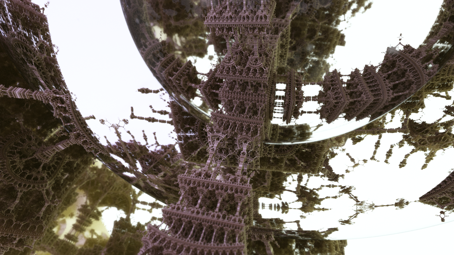
This diffuse material comes out great, only issue being that it needs like 100+ samples before you really get something that starts to look smooth. You can also see some little variations in the noise in these two images - this is the interaction of the ray origin jitter in the DoF logic and the dielectrics, which mess with the amount of ray divergence that you will see.
Future Directions
One of the major things I want investigate from here is spectral rendering. This eschews the concept of using RGB tuples as your primary representation, and instead represents light as spectral distributions. In doing this, you can start to see a wavelength dependence in the behavior of rays interacting with materials. This manifests in things like chromatic aberration, and the rainbow colored dispersion through the prism on the cover of Pink Floyd's The Dark Side of the Moon. This is kind of on the back burner while I learn Vulkan and work more on Voraldo.